Meghalaya State Electricity Board (MSEB)


  • Customer : Techno Electric & Eng. CO.LTD, STERLITE POWER TRANSMISSION LTD
  • Project start: August 2024
  • Project completion: December 2024
  • Substation voltage: 220/132/33 kV
  • Project Type: Substation Automation System
  • Protocols Used: Modbus RTU, IEC61850, IEC60870-5-104, SNTP
  • Automation Software and Hardware: iGW, iRTU, iRTUe, iControl SCADA software

  • Project Description


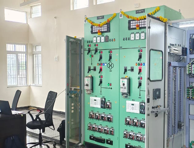
    MSEB is an Indian state utility in Meghalaya situated in north eastern part of India

    This is a 220/132/33kV substation.

    It includes communication with protection relay, energy meters using Gateway and SCADA software.The local SCADAis used for monitoring and control operation of the switch gear equipment.

    The project involves relays communicating in IEC61850, energy meters communicating in Modbus.

    The substation automation system (SAS) system is reading data from substation auxiliary like AC distribution board (ACDB), DC distribution board (DCDB)and battery chargers.

    The local SCADA shows online status of the substation by means of SLD screen shown in the iControl SCADA. There are also bay wise screens, individual bay screens, metering information screen and architecture screen shown in the SCADA.These screen displays the information of the switch gear equipment and metering details.


    Silent features of this project


  • All the automation related devices like relays, SCADA servers, Gateway are time Synchronised with the GPS clock using SNTP protocol.
  • The project implements a robust electrical power system schematic designed for real-time monitoring, protection, and control of grid components operating at the 230kV level.
  • On LAN A, the system integrates critical assets such as transformers, bus couplers, bus bars, reactors, and feeders, each equipped with Boundary Condition Units (BCUs) and protection relays like Differential (DIFF), Reference (REF), and Overload Current Level – External Fault (OLC-EF) relays.
  • Transformer Voltage Monitoring (TVM) units and RJ45 Ethernet Switches ensure accurate measurement and seamless data transmission to the Substation Automation System (SAS). Connections are facilitated through RJ45 connectors, fiber optic cables, and copper links for reliability.
  • The LAN B segment mirrors redundancy and resilience, hosting 230kV bus couplers, reactors, feeders, BCUs, differential relays, TVM units, and Line Conditioning Boards (LCBs). Communication is supported by dedicated Ethernet Switches interfacing with external systems.
  • The architecture employs dual ingress gateways (IGW-1 and IGW-2) along with GPS synchronization to enhance system reliability, time accuracy, and operational integrity.
  • Redundancy and status monitoring are provided through server-side supervision, which displays key information such as Active Status, Peer Status, and Role assignments.
  • Overall, the schematic demonstrates a modernized and redundant power system communication design, ensuring high availability, seamless integration, and secure data flow between protection devices, monitoring units, and control servers.