Project Details
- Customer : Karnataka Power Transmission Corporation Limited (KPTCL)
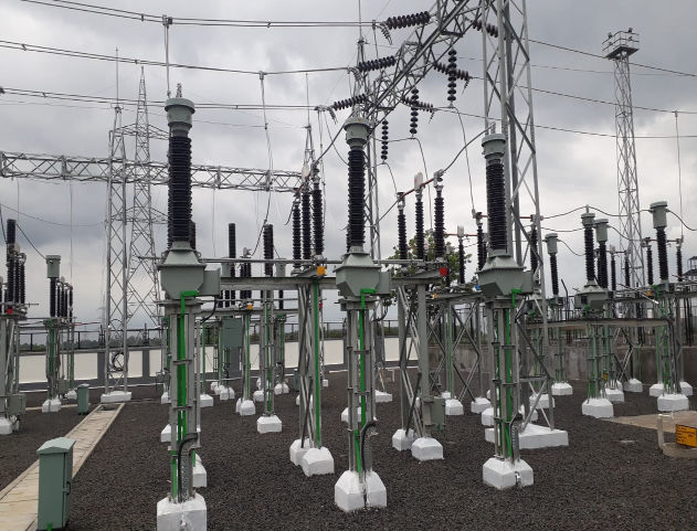
- Substation voltage : 66/11 kV
- Project Type : Substation Automation System
- Protocols Used : IEC61850, IEC60870-5-104, Modbus RTU
Project Description
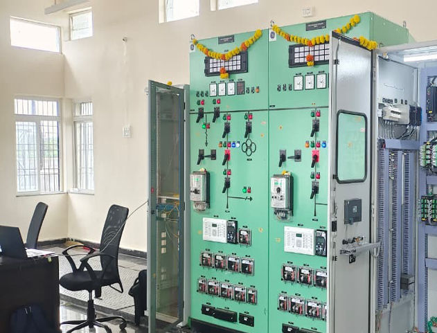
KPTCL is the state transmission utility of Karnataka. The 66/11 kV Mandur substation project provides complete substation automation system.
Key Features
- Complete substation automation system for 66/11 kV substation
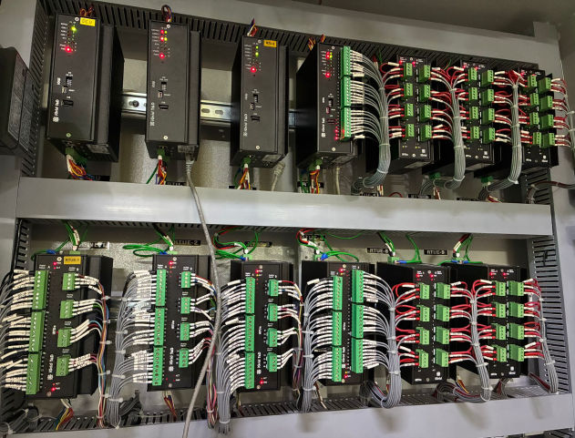
- IEC61850 protocol communication with protection relays
- IEC60870-5-104 data transmission to remote control center
- Modbus RTU communication with energy meters
- Local SCADA monitoring with SLD screens for real-time status
Project Gallery
More Project References

132 kV Substations Automation with 61850 at AEGCL (Assam)

400 kv HV Substations Automation at TANTRANSCO (Tamil Nadu)

220/132 kv HV Substations with RTU and IEC 61850 SCADA at MPPTCL (Madhya Pradesh)

220/132 kv 61850 Substation with ADLS at CSPTCL (Chatisgarh)

220 kV GIS 61850 substation at PTCUL (Uttarakand)